
Why Traditional Highway Drainage Is Failing Modern Commuters
Regional commuter corridors are increasingly exposed to a sequence of hazards that older drainage networks were not designed to manage together. A short, intense cloudburst can overwhelm inlets, while already saturated soils prevent surrounding ground from absorbing additional water. In July 2026, Nigeria”s meteorological agency warned that heavy rainfall had saturated soils across many areas, leaving limited capacity for further infiltration and increasing the risk of rapid surface runoff, transport disruption, and infrastructure damage. The same hydrological pattern can affect highway systems anywhere intense storms arrive after prolonged wet weather.
For decades, highway drainage was commonly organized around a simple objective: collect runoff quickly and discharge it away from the pavement through gutters, culverts, pipes, and outfalls. That approach remains essential, but a single large conveyance system can become a point of failure when rainfall intensity exceeds its design assumptions or when downstream channels are already full. Modern transportation departments are therefore moving toward watershed resilience. Instead of treating every drop as a nuisance to be removed, planners are combining gray infrastructure with soils, vegetation, terraces, detention areas, and carefully controlled overflow routes that slow water before it reaches the travel lanes.
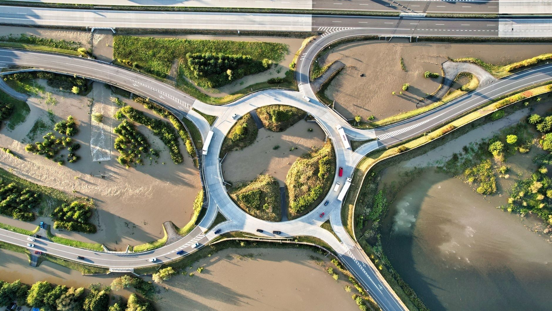
Moving Beyond Concrete Pipes to Modern Nature-Based Engineering
Conventional drainage concentrates water. A curb inlet, pipe, and outfall may perform efficiently during ordinary storms, yet the same concentration can produce destructive peak flows at one location. When the receiving ditch or stream cannot accept that discharge, water backs up toward the roadway, scours embankments, or carries sediment into an underpass. Nature-based drainage distributes the task across a wider corridor. Bioswales, vegetated ditches, amended soils, infiltration areas, and detention pockets temporarily store runoff and release it more gradually.
The most dependable strategy is usually hybrid rather than purely green or purely gray. Pipes and culverts provide predictable conveyance for frequent storms and controlled bypasses during larger events. Green features reduce the volume and speed that those structures must handle. The result is a layered system in which peak flow is attenuated before runoff can overtop shoulders, erode slopes, or enter a low point faster than pumps and inlets can respond. Designers should model the interaction between surface storage, infiltration, underdrains, overflow structures, and major drainage paths rather than assessing each element in isolation.
Federal guidance provides a useful technical foundation for this integrated approach. The Federal Highway Administration”s urban drainage manual addresses rainfall and runoff, pavement drainage, gutter flow, inlet design, roadside ditches, storm-drain piping, detention facilities, and water-quality practices. Its stormwater dewatering and treatment guidance also defines the terminology and compliance framework surrounding best management practices, erosion and sediment control, chemical treatment, the National Pollutant Discharge Elimination System, and total suspended solids. Engineers can consult the agency”s stormwater dewatering guidance when developing treatment trains and construction-phase controls.
- Capture: Direct sheet flow into vegetated edges, inlets, or shallow storage areas before it gains erosive speed.
- Slow: Use check structures, roughness, terraces, and broad flow paths to reduce peak discharge.
- Treat: Retain sediment and pollutants through vegetation, engineered soils, and controlled residence time.
- Convey: Maintain culverts, pipes, and overflow channels for storms that exceed green-infrastructure capacity.
- Recover: Design inspection access so sediment removal, vegetation management, and outlet repairs can occur without closing the corridor for extended periods.
Comparing Conventional Culverts and Vegetated Highway Buffers
A culvert is a valuable conveyance component, but it generally transfers concentrated flow from one side of a road to the other. A vegetated highway buffer performs a broader set of functions: it spreads runoff, increases hydraulic roughness, traps sediment, supports infiltration where soils permit, and can protect the embankment from direct high-velocity discharge. Neither feature should be treated as a universal replacement for the other. The correct choice depends on drainage area, grade, soil permeability, groundwater conditions, available right of way, maintenance capacity, and the consequences of failure.
| Performance factor | Conventional culvert | Vegetated highway buffer |
|---|---|---|
| Peak flow response | Conveys water efficiently but can concentrate discharge and create downstream surges | Temporarily stores and slows runoff across a wider area |
| Sediment retention | Limited unless paired with forebays, sumps, or separate treatment | Vegetation and engineered media can capture sediment before water reaches outlets |
| Maintenance footprint | Requires inlet, barrel, outlet, and scour inspection | Requires mowing or planting management, sediment removal, and outlet inspection |
| Failure mode | Blockage, inlet bypass, overtopping, or outlet scour | Clogging, erosion, vegetation loss, or excessive standing water |
| Right-of-way need | Relatively compact underground or crossing installation | Requires linear surface space and safe access for maintenance |
Caltrans” 2020 biofiltration swale design guidance illustrates how a vegetated system can be engineered rather than treated as informal landscaping. These swales are soil-based low-impact development practices approved for Caltrans facilities. They convey highway drainage while treating water-quality volume and flow. Design considerations include hydraulic residence time, sizing for design storms, soil amendments, infiltration, energy dissipation, excessive flows, bridge-end runoff, safety, and maintenance. Those details matter because a swale that looks attractive but lacks adequate storage, outlet protection, or overflow capacity can become a hazard during the very storm it was intended to manage.
Engineered soil blends are particularly important across shoulders and embankments. A carefully specified mix can balance infiltration with structural stability, support healthy vegetation, and reduce prolonged ponding. The objective is not to force all water into the ground. In locations with shallow groundwater, contaminated soils, expansive clays, or unstable slopes, underdrains and controlled discharge may be preferable. The design should define where water goes when the soil profile is saturated, how quickly the swale drains after an event, and how standing water will be prevented from affecting pavement, pedestrian routes, or roadside safety.
Deploying Terraced Basins and Multi-Stage Edge Defenses
Terraced basins convert a long, uncontrolled slope into a sequence of manageable storage zones. Rather than allowing runoff to accelerate continuously toward an underpass, planners can grade the highway easement into shallow steps separated by level spreaders, check berms, or reinforced transitions. Each terrace temporarily holds water, reduces flow velocity, and gives sediment an opportunity to settle. The approach is especially useful where a corridor passes through a steep catchment and where downstream damage would be concentrated at a bridge approach, interchange, or depressed roadway.
Retention terraces should be designed as part of a complete drainage sequence. A forebay or sediment basin can receive the first dirty flush, while downstream cells provide additional detention and treatment. Overflow weirs, armored spillways, and emergency bypasses are necessary because terraces must fail safely when rainfall exceeds the design event. Access roads and inspection points should be included from the start. Without them, sediment accumulation can reduce storage capacity and small erosion defects can develop into a corridor-scale failure.
Municipal stormwater manuals offer useful precedent for this type of distributed control. Knoxville”s engineering references, for example, draw on a broad body of material covering watershed management, hydraulics, detention, wetlands, porous pavement, biofiltration, erosion control, and Caltrans stormwater handbooks. The city”s BMP reference collection demonstrates why regional agencies should adapt established runoff-control principles to local soils, rainfall, slopes, and maintenance resources rather than copy a standard detail without review.
- Map the contributing watershed: Identify pavement, cut slopes, adjacent development, natural drainage lines, and low points that can deliver water to the corridor.
- Set the major flow path: Preserve a clearly defined route for extreme runoff so water cannot migrate unpredictably across travel lanes or private property.
- Grade storage tiers: Use shallow basins, level spreaders, and stable berms to divide the slope into stages with measurable storage and safe overflow points.
- Protect each transition: Install erosion-resistant surfaces, energy dissipation, vegetation, or structural reinforcement where water changes direction or elevation.
- Connect to gray drainage: Link terraces to culverts, inlets, underdrains, and detention outlets so stored water is released at a controlled rate.
- Plan long-term stewardship: Assign responsibility for inspections, sediment removal, vegetation replacement, outlet clearing, and post-storm review before construction begins.
Elevated Corridors and Dual-Purpose Barrier Systems
In some locations, the roadway itself can become part of the flood defense. A raised embankment, reinforced retaining wall, or coordinated elevation of roadway and sidewalk may prevent floodwater from reaching critical facilities while preserving an emergency route. The Federal Highway Administration”s Hydraulic Engineering Circular No. 17 provides a framework for evaluating transportation infrastructure in riverine flood environments, including extreme events, climate change, land-use change, uncertainty, and resilience. Its graduated analysis approach helps agencies match the depth of investigation to the importance and risk of the corridor.
Elevation is not automatically beneficial. Raising only the pavement beside existing buildings can redirect water toward properties, restrict accessibility, complicate utilities, and create maintenance or business impacts. Boston”s climate-resilient raised-roadway guidance emphasizes site-specific studies, flood-side consequences, setbacks, easements, pedestrian and bicycle access, utility coordination, and green stormwater management. A barrier system should therefore be designed as a public-space and drainage project, not merely as a taller road section.
- Preserve emergency continuity: Verify that the elevated route remains passable for emergency vehicles during the targeted flood scenario.
- Protect access: Integrate sidewalks, crossings, bicycle movement, transit stops, ramps, and accessible grades into the vertical design.
- Manage both sides: Model where water accumulates on the protected side and where flood-side communities may require separate defenses or evacuation planning.
- Coordinate utilities: Review gravity sewers, water lines, power, communications, drainage outlets, and maintenance access before finalizing the profile.
- Use adaptable details: Allow for future upgrades, revised flood elevations, replaceable barriers, and changes in land use or storm intensity.
Building Arteries Ready for the Next Hundred-Year Deluge
Reliable commuter corridors will come from systems that work with natural hydrology while retaining the precision of modern drainage engineering. Bioswales, terraces, detention cells, and vegetated buffers can reduce runoff speed and sediment loads. Culverts, pipes, retaining structures, inlets, and protected overflow routes then provide dependable conveyance when rainfall exceeds ordinary capacity. Together, these measures create multiple lines of defense instead of placing the entire corridor”s performance on one inlet, one culvert, or one downstream channel.
The practical next step is to prioritize the locations where a modest intervention can prevent a major outage: saturated low points, bridge approaches, underpasses, steep embankments, blocked culvert crossings, and routes that serve hospitals, evacuation areas, industrial centers, or large commuter populations. Agencies should combine updated rainfall and flood modeling with field inspections, maintenance records, emergency response experience, and community knowledge. Preemptive green mitigation may require more planning at the outset, but it can reduce repeated washouts, emergency reconstruction, traffic disruption, and escalating repair costs. The goal is steady progress: identify the weakest links, add distributed storage and safe conveyance, elevate critical segments where justified, and maintain every layer so the corridor remains useful when the next exceptional storm arrives.

